
{{product.productLabel}} {{product.model}}
{{#if product.featureValues}}{{product.productPrice.formattedPrice}} {{#if product.productPrice.priceType === "PRICE_RANGE" }} - {{product.productPrice.formattedPriceMax}} {{/if}}
{{#each product.specData:i}}
{{name}}: {{value}}
{{#i!=(product.specData.length-1)}}
{{/end}}
{{/each}}
{{{product.idpText}}}
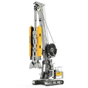
Drilling depth: 0 m - 80 m
Motor power: 320 kW
Thrust: 450 kN - 600 kN
... simplifies loading for transport and assembly
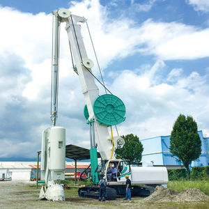
Applications
- Slurry wall installation with clamshell grab: excavation of slurry wall panels using clamshell grab
Technical ...
Liebherr
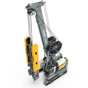
Drilling depth: 0 m - 80 m
Motor power: 390 kW
Thrust: 450 kN - 600 kN
... Overview
The carrier machine LBX 600 unplugged is designed for slurry
wall (
diaphragm
wall) construction on urban and noise-sensitive jobsites. The battery-powered "unplugged" version produces ...
Liebherr
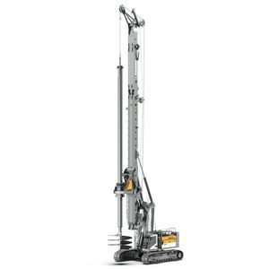
Drilling diameter: 0 mm - 4,800 mm
Drilling depth: 0 m - 120.4 m
Motor power: 565 kW
... Overview
The LB 55
drilling
rig from Liebherr is a heavy-duty rotary
drilling
rig designed for deep foundation works. It supports multiple
drilling methods — Kelly ...
Liebherr
Drilling depth: 30 m/s²
... Depth of excavation30 m Width of trench400 ÷ 800 mm Lenght of trench2200 ÷ 2500 mm Kelly rotation± 45° Weight in working condition40 t ...
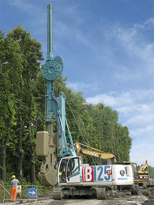
CASAGRANDE - Foundation Division
Drilling depth: 80 m/s²
... Max depth50 m (80 m optional) Width of trench600 ÷ 1500 mm Lenght of trench2500 ÷ 3200 mm Weight in working condition without grab68500 kg ...
CASAGRANDE - Foundation Division
the best suppliers